BLF-Tech LLC

Ladder Diagrams - the starting point for learning PLCs
The first designers of PLCs quickly recognized that maintenance electricians would need to troubleshoot their plants' new control systems. The Ladder Diagram programming language was adopted in an effort to keep things simple.
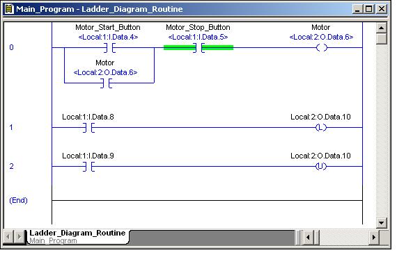
Electricians have long been taught that the familiar "switches and coils" schematics shown on the screen actually represent the real-world input and output devices located in the field. Handy "green on the screen" highlights have been explained as "power flow" - which can be traced (like electricity) through the "contacts" of the PLC's ladder logic program.
This watered down, traditional type of PLC training is all nonsense – but at least it does enable the maintenance electricians to find some simple beginner-level types of problems. Unfortunately the term "beginner-level" doesn't really fit most of the problems encountered out in the real world.
But - love or hate it – the Ladder Diagram programming language is an essential part of learning PLCs. The main objective is to understand what's REALLY happening "under the hood" when the PLC processor executes this type of code. Once you have a handle on that piece of the puzzle, then you can apply that knowledge toward understanding Structured Text, Function Block Diagrams, Sequential Function Charts, Equipment Phases, and whatever else the original ControlLogix programmer decided to throw at you.
Reference material on Allen-Bradley's website
For more information, or to register for a class, contact us at:
702-418-4634 text - phone
bferry@blftech.com - email
702-418-4634 text - phone
bferry@blftech.com - email